Three Effective Distributed Database Deployment Topologies for Dual Data Center Challenges
May 9, 2024
YugabyteDB is engineered for high availability, scalability, and fault tolerance by distributing data and request processing across multiple fault domains. However, even with this distributed architecture, two significant challenges emerge when operating in a two-datacenter or two-region model:
- The risk of a complete regional outage (with an arbitrary majority) leading to the loss of a distributed quorum
- The potential for data loss due to asynchronous data replication between data centers or regions.
To overcome these challenges, YugabyteDB supports various deployment topologies designed to meet specific high availability and disaster recovery needs. In this blog post, we will explore these deployment options, examining both happy path scenarios and failure scenarios, and discuss the trade-offs between recovery time objective (RTO), recovery point objective (RPO), latency, and other factors.
The Odd Quorum Conundrum in a Two Data Center Model
In YugabyteDB, a quorum is the minimum number of replicas that must participate in a write transaction to ensure data consistency and availability. Typically, an odd quorum is required to avoid “split-brain” scenarios and ensure that there is a clear majority for decision-making. However, maintaining this odd quorum in a two-datacenter model is challenging because it involves having an arbitrary majority in one datacenter. If the data center with the majority of replicas goes down, it will affect the availability of the service.
The Challenge With Adding a Third Region
The ideal solution to this problem is by adding a third region. However, many enterprises still operate with two data centers, which must be kept on par and regularly updated as part of their business continuity planning (BCP). Executing BCP demands considerable planning, time, and effort. In addition, regulatory requirements require enterprises to alternate between primary and secondary roles of data centers every six months to ensure readiness for a disaster. Let’s look at how different deployment topologies can help solve this issue.
Deployment Topologies
In the following section, we’ll assign names to regions to identify easily. In the context of a self-managed infrastructure, the term “region” refers to a data center.
| Regions / Data Centers | Mumbai, Delhi | |
| Classification | Region1 / DC1 | Mumbai |
| Region2 / DC2 | Delhi | |
1: xCluster
A database is distributed across multiple availability zones in a region/data center, with each region having its own isolated setup.
| Regions / Data Centers | Mumbai, Delhi | |
| Classification | Primary | Mumbai |
| Secondary | Delhi | |
| Fault Domains | Primary | H1a, H1b, and H1c (isolated domains within a region) |
| Secondary | H2a, H2b, and H2c (isolated domains within a region) | |
| Topology | xCluster | |
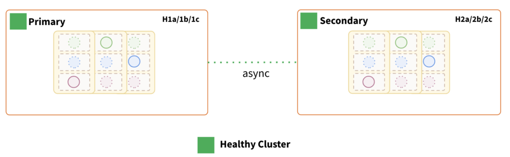
Key Points:
- Each region has its own isolated YugabyteDB cluster.
- Each cluster ensures fault tolerance at the availability zone level within a region.
- Asynchronous cross-cluster (xCluster) data replication between “primary” and “secondary” regions.
- Data replication can be either unidirectional or bidirectional.
- Each cluster can be scaled independently.
- Tunable reads can be enabled for each cluster.
Now let’s go over each of the failure scenarios.
Primary Region Failure:
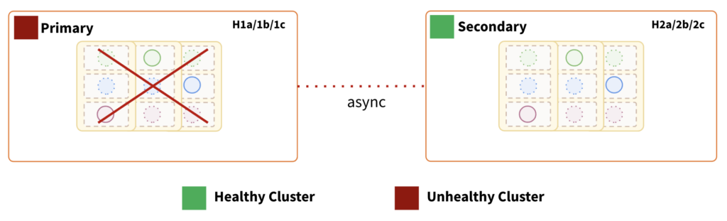
Impact:
- Depending on the direction of replication, the “secondary” data center can be quickly utilized to continue serving the traffic.
- If the replication topology is a unidirectional< transactional xCluster from “primary” to “secondary,” the “secondary” can be promoted as primary once the “safe time” is determined.
- If the replication topology is bidirectional, app traffic must be routed to the “secondary” based on acceptable data loss.
- RTO in a unidirectional xCluster is determined by the amount of time required to transition from the “primary” to “secondary” cluster. At this time, we do not provide auto-failover features at the driver level. Therefore, the application or application-ops team must handle it. The normal DR activation procedure is usually followed in this.
- RPO is determined by the replication lag between the two regions/data centers. Because of the async data replication between them, this topology cannot guarantee a zero RPO.
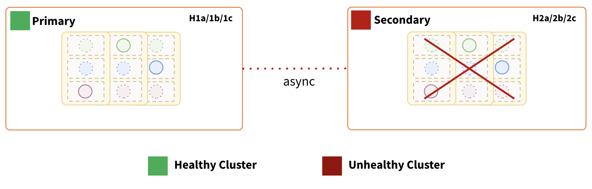
Secondary Region Failure:
 Impact:
- Depending on the replication direction, the other cluster can be quickly utilized to continue serving the traffic. The other points of impact are the same as the previous failure scenario.
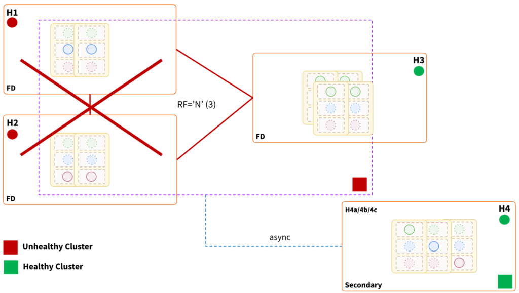
2: Globally Distributed
A database that is distributed across multiple fault domains between two regions/ data centers.
| Regions/Data Centers | Mumbai, Delhi | |
| Fault Domains | Mumbai | H1 |
| Mumbai | H2 (isolated domain within the same region) | |
| Delhi | H3 | |
| Delhi | H4 (isolated domain within the same region) | |
| Replication Factor (Primary)Total: 3 | H1 | 1 replica (data copy) |
| H2 | 1 replica | |
| H3 | 1 replica | |
| Replication Factor(Secondary)Failover cluster during a disasterTotal: 3 | H4 (H4a,4b,4c) | 3 replicas |
| Topology | Globally distributed | |
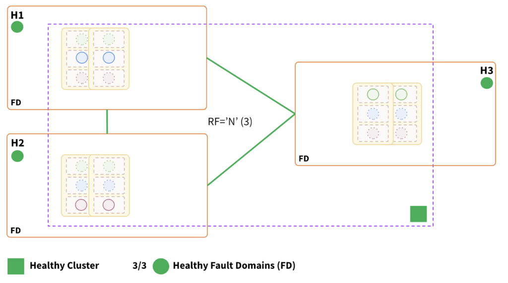
Key Points:
- A single cluster is distributed across all three fault domains (H1, H2, and H3).
- The topology can withstand a single fault domain failure.
- The two nearby fault domains have a proportional effect on write latency.
- Data and request processing are distributed equally across the three fault domains.
- Horizontally scalable and tunable reads can be enabled.
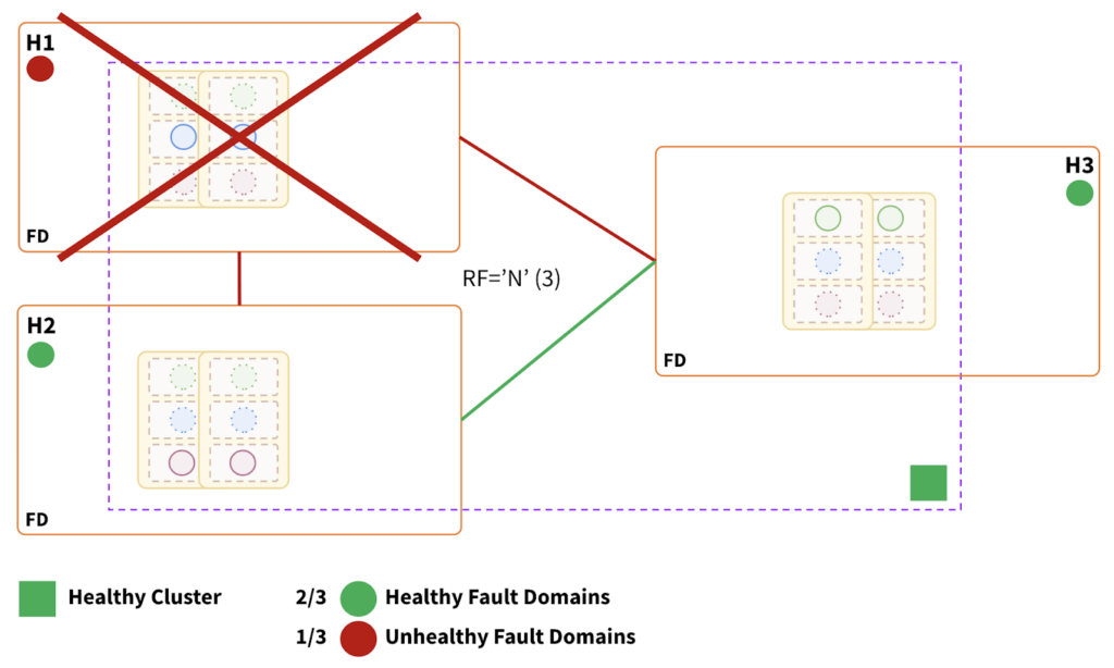
Fault Domain Failure:
 Impact:
- Topology can withstand a single fault domain failure.
- The cluster remains fully operational, as two-thirds of the fault domains are healthy.
- RTO is internally balanced because failure causes leader elections in the surviving fault domains.
- RTO ranges from 3 to a few seconds, depending on the number of tablets.
- May incur a slightly higher latency as H3 is relatively placed farther compared to the placement of H1 and H2.
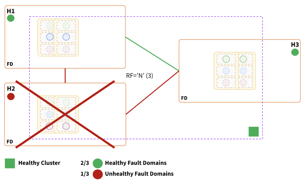
Region Failure:
Impact:
- Topology can withstand a region failure that hosts minority replicas.
- The cluster is fully operational, as two-thirds of the fault domains are healthy.
- RTO is internally balanced because failure causes leader elections in the surviving fault domains.
- RTO ranges from 3 to a few seconds, depending on the number of tablets.

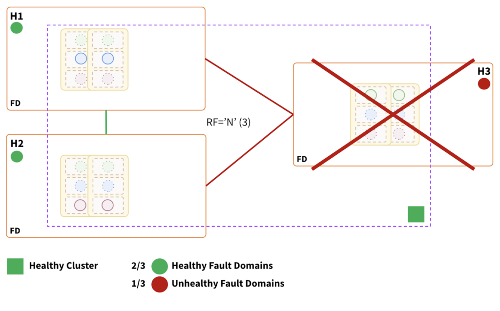
Impact:
- At least two of the three fault domains must be healthy for the cluster to be healthy. This region hosts two-thirds of the replicas, so consistent reads and writes will be impacted.
- The cluster state would be unhealthy and inoperable.
- Need to fail over to the “secondary” cluster (depicted below), which will asynchronously receive data from the primary cluster. At this time, we do not provide auto-failover features at the driver level. Therefore, the application or application-ops team must handle it.
- RTO is determined by the time required to transition from “primary” to “secondary”.
- RPO is determined by the replication lag between the two cluster instances. Because of the async data replication between the two instances, this topology cannot guarantee a zero RPO.
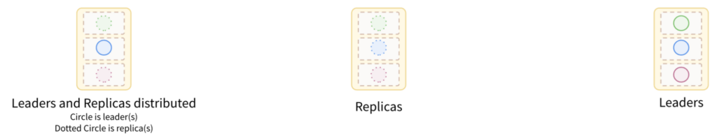
3: Globally distributed with pinned leaders
A database distributed across multiple fault domains between two regions/ data centers, with leaders and replicas pinned to reduce the RPO as much as possible during a disaster.
| Regions/Data Centers | Mumbai, Delhi | |
| Fault Domains* | Mumbai | H1 |
| Mumbai | H2 (isolated domain within the same region) | |
| Delhi(H3a,3b) | H3 | |
| Replication Factor(Primary)Total: 3 | H1 | 1 replica |
| H3 | 2 replicas | |
| Replication Factor(Secondary)Total: 3 | H2(H2a,2b,2c) | 3 replicas |
| Topology | Globally distributed with pinned leaders | |
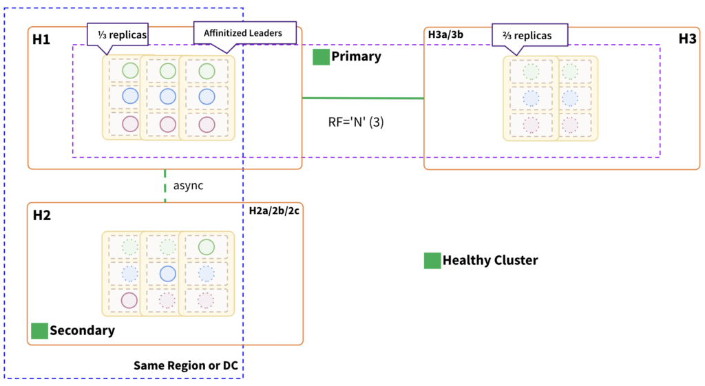
Key Points:
- A single cluster is distributed across two regions (H1 and H3)./li>
- Tablet leaders are pinned to the H1 fault domain nodes.
- H1 keeps one-third of the replicas, while H3 keeps the other two-thirds.
- H3 is logically divided into two fault domains, H3a and H3b, in order to retain two-thirds of the replica.
- A secondary cluster is maintained in H2 and is located in the same region or data center as the primary cluster’s pinned leaders.
- As tablet leaders are pinned to H1, secondary cluster’s async replication will be in near real time as it is co-located in the same region.
- Writes may experience additional latency as the consensus must reach one of the fault domains in H3.
- As tablet leaders are pinned to H1, which solely serves consistent reads and writes, we need to factor in additional resources in H1.
Region Failure:
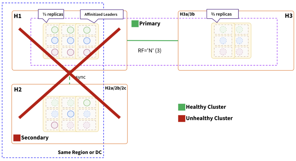
Impact:
- Topology can withstand failure of the H1 region, which contains minority replicas.
- RTO is internally balanced because failure causes leader elections in the surviving H3 fault domains.
- RTO ranges from 3 to a few seconds, depending on the number of tablets.
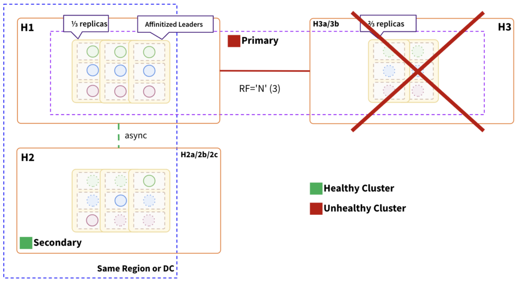
Impact:
- In order for the cluster to be healthy, at least two of the three fault domains must be healthy. This region hosts two-thirds of the replicas, so consistent reads and writes will be impacted.
- Primary cluster will be unhealthy and inoperable.
- Need to fail over to the “secondary” cluster, which will asynchronously receive data from the primary cluster. At this time, we do not provide auto-failover features at the driver level. Therefore, the application or application-ops team must handle it.
- RTO is determined by the time required to transition from “primary” to “secondary”.
- RPO is almost negligible as the async replication is near real-time and co-located in the same region.
Summary:
Operating a distributed database system in a two-data-center model presents two significant challenges: the inability to achieve an odd quorum in the event of a total regional outage, which may result in data loss or inconsistency during recovery. These challenges emphasize the importance of carefully considering the trade-offs and implementing appropriate failover mechanisms to ensure data consistency, availability, and fault tolerance in distributed database environments.
| Topology | Mumbai disruption | Delhi disruption |
| RTO | ||
| xCluster – Unidirectional | Time required to swing the traffic to secondary | No impact |
| xCluster – Bidirectional | No impact | No impact |
| Globally distributed | Time required to swing the traffic to secondary | Near zero * |
| Globally distributed with pinned leaders | Near zero * | Time required to swing the traffic to secondary |
| * ~3 to a few seconds for the tablet leaders to get balanced in the surviving FDs | ||
| RPO | ||
| xCluster – Unidirectional | Replica lag * | No impact |
| xCluster – Bidirectional/td> | Replica lag * | Replica lag * |
| Globally distributed | Replica lag * | No impact |
| Globally distributed with pinned leaders | No impact | Near zero ** |
| *Determined by the replication lag between two regions. ** Async replication is near real-time and co-located in the same region | ||
| Topology | Parameters | |||
| Fault Tolerance | Operational Efficiency | Performance | Transactional Atomicity Guarantees | |
| xCluster – Unidirectional | Infra Level |
|
| Guaranteed while failover to secondary |
| xCluster – Bidirectional | Region and Infra Level |
|
| Not guaranteed |
| Globally distributed | Region and Infra Level * |
|
| Guaranteed while failover to secondary |
| Globally distributed with pinned leaders | Region and Infra Level * |
|
| Guaranteed while failover to secondary |
| *Withstand failure of minority replica region | ||||
Additional Resources:
- Build global applications: Learn how to design globally distributed applications using simple patterns (YugabyteDB documentation)
- Synchronous replication using the Raft consensus protocol (YugabyteDB documentation)
- xCluster replication: Asynchronous replication between independent YugabyteDB universes (YugabyteDB documentation)
- Geo-Distribution in YugabyteDB: Engineering Around the Physics of Latency
Ready to experience the power and simplicity of YugabyteDB for yourself?
Sign up for our free cloud DBaaS offering today at cloud.yugabyte.com. No credit card required, just pure database innovation waiting to be unleashed!
 Ready to experience the power and simplicity of YugabyteDB for yourself? Sign up for our free cloud DBaaS offering today at cloud.yugabyte.com. No credit card required, just pure database innovation waiting to be unleashed!

